Cabling

Requirements
- A 630/6200 wireloom
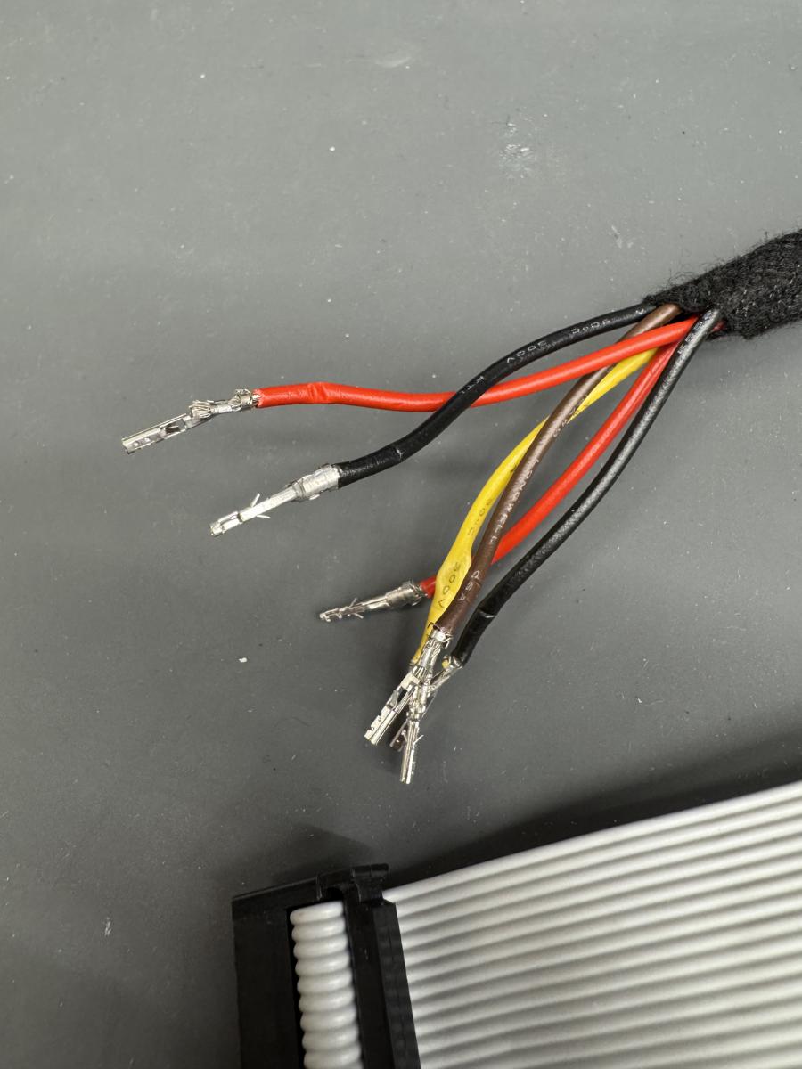
- 6x 35cm 18AWG cables (2x red, 2x black, 1x brown and 1x yellow)
(can be taken from the original 630/6200 wireloom)
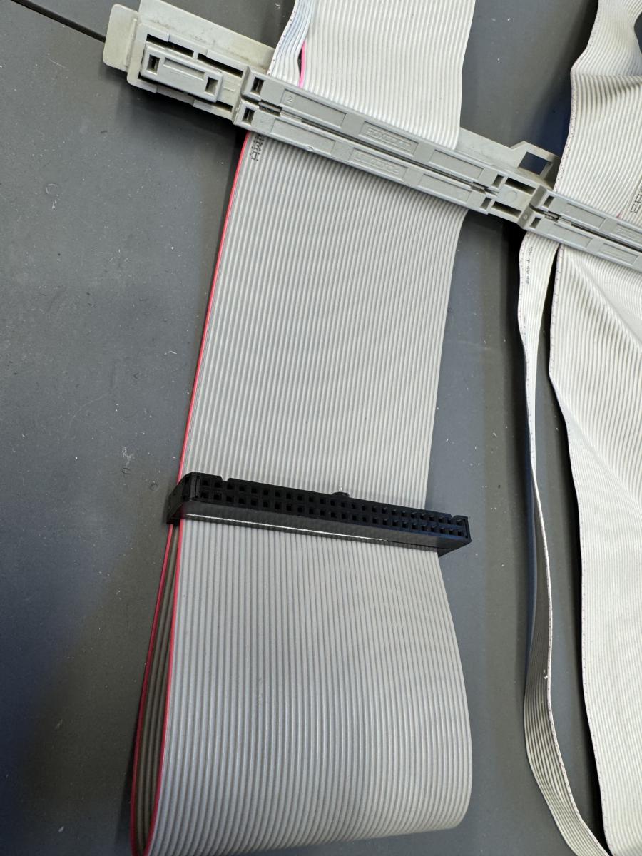
- 50P IDC CABLE (25cm)
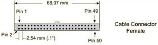
- 50P SCSI connector (female)
- MOLEX 2x6P Microfit connector + pins
(included in the LCD Takky KIT)
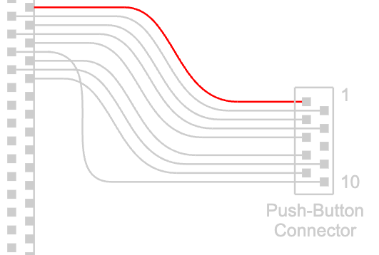
- Optional: 20cm 10P Card Edge Connector + 10P IDC cable. Can be reused from the Color Classic wireloom.
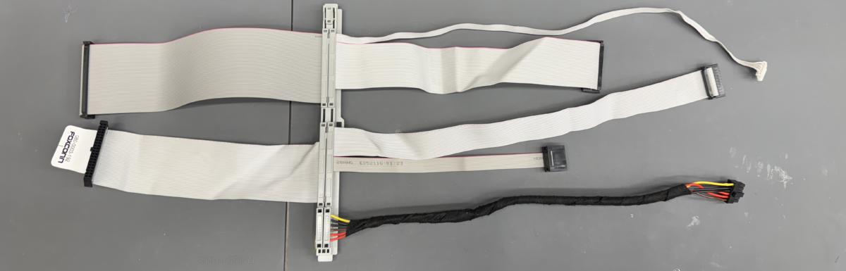
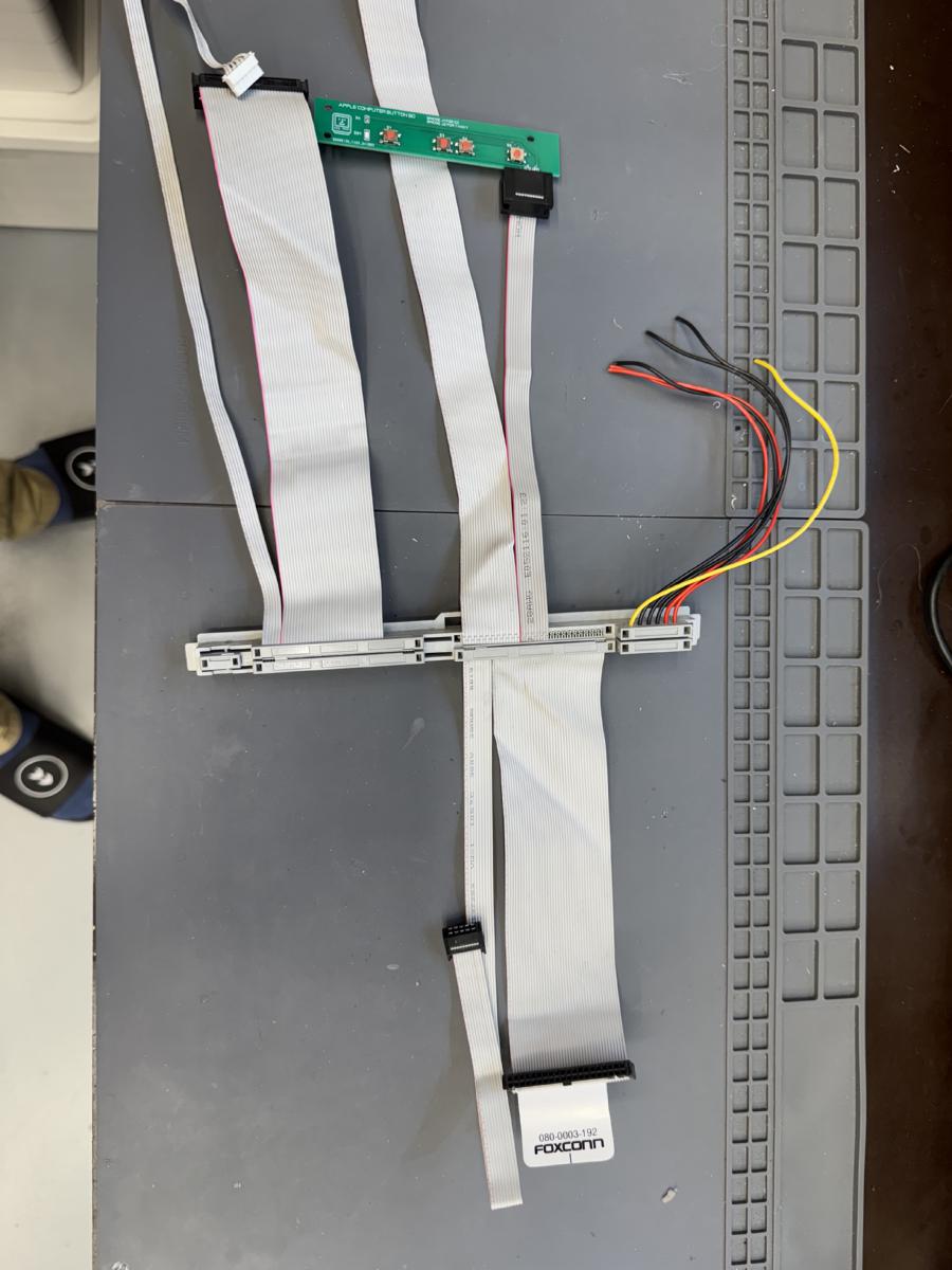
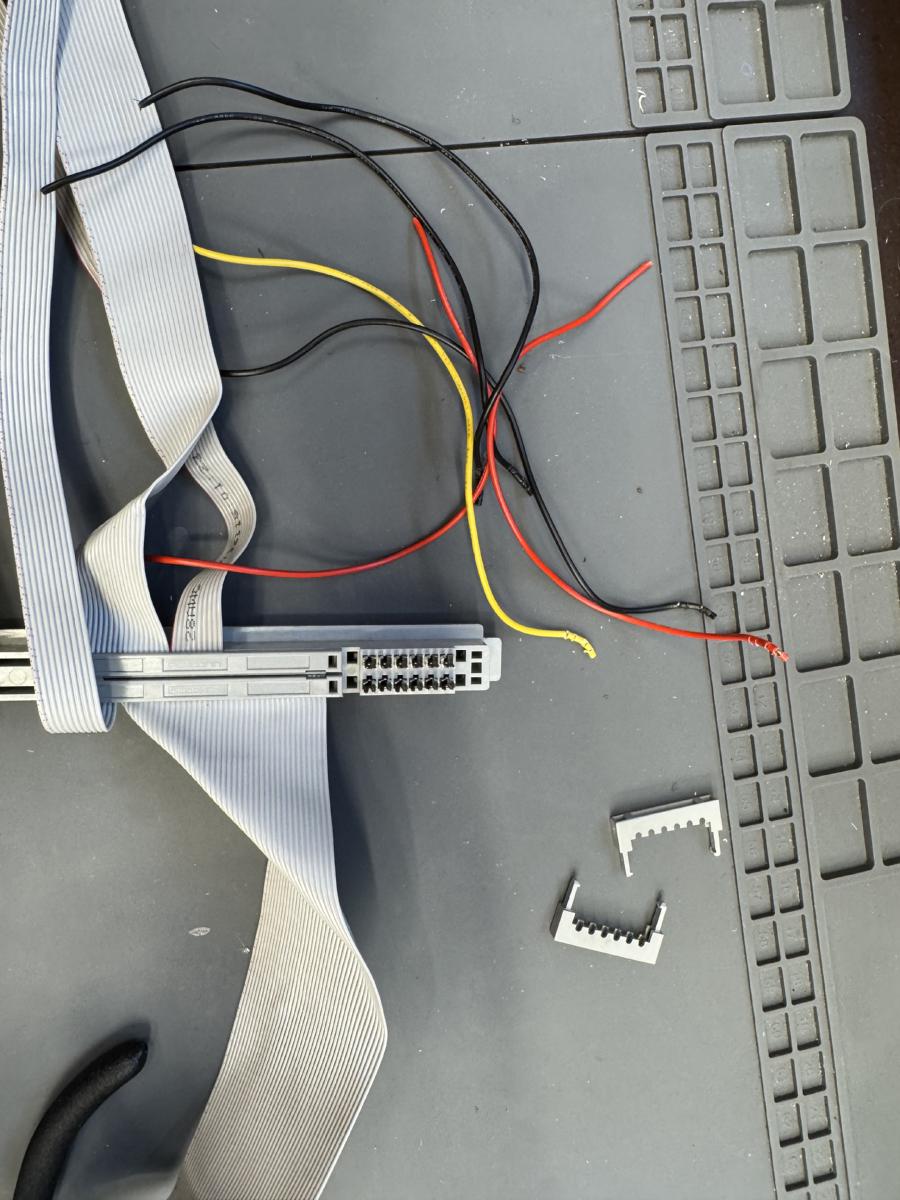
LC630 wireloom


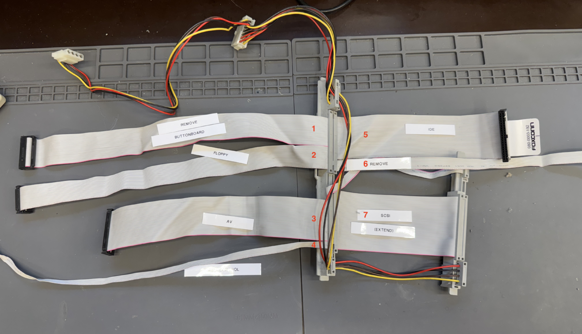
The following changes are needed
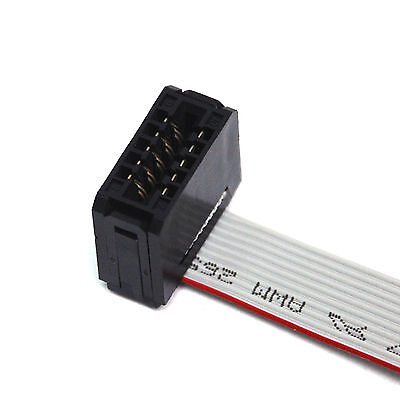
1) Need to be replaced by a smaller cable.
6) Need to be removed
7) SCSI - Need to be extended to 25cm
Optional:
2) Floppydrive cable can be removed if you are not going to use the floppydrive


These cables do not need any changes:
3) AV cable - no changed needed
4) PSU control - no changed needed
5) IDE cable - no changed needed

Step 1 - Remove cables

Some of the flatcables are not used, or are too short, or do have a different pinout. Therefor we start by removing some of the cables from the LC630 (or equivalent) wireloom.

Remove the flatcables labeled:
[1] - BUTTONBOARD
[6] - TUNER
[7] - SCSI


Step 2 - Buttonboard
Because we want to reuse the frontbuttons of the Color Classic chassis we need to transfer the buttonboard cable from the original Color Classic wireloom.

Pin 1 (the red labeled cable) starts right next to the floppycable.

-----------------------------------------------------
Do not use the original buttonboard using this method. We designed a new buttonboard which matches the different pinout. If you want to use the original buttonboard you need to cut out line 6 and move line 10 to pin 6.

-----------------------------------------------------
Step 3 - Extend SCSI cable
The LC630 SCSI [7] cable is originally used for a CDROM drive, so it has the wrong connector and is too short for the new situation. We need to extend the SCSI cable to 25cm and add a 50P IDC connector to it.

Pin 1 (red labeled) should be connected to the female 2.54mm IDC connector to the upperleft position:


Step 4 - Power cabling
The current power cables are too short, so they need to be extended to 35cm.
Remove the current powercables.
The order of the cables in the connector is from outside to inside.

+5V
+5V
+3.3V
GND
GND
+12V


The endresult should look like this


Step 5 - Attach 12P Microfit connector to the powerlines
Clamp the MOLEX Microfit pins to the cables and attach the connector like in the photo.
The Molex partnumber to be used on our Takky board is: 43025-1200


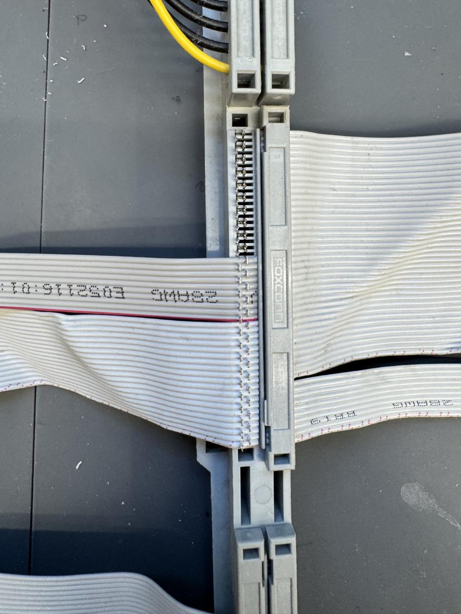
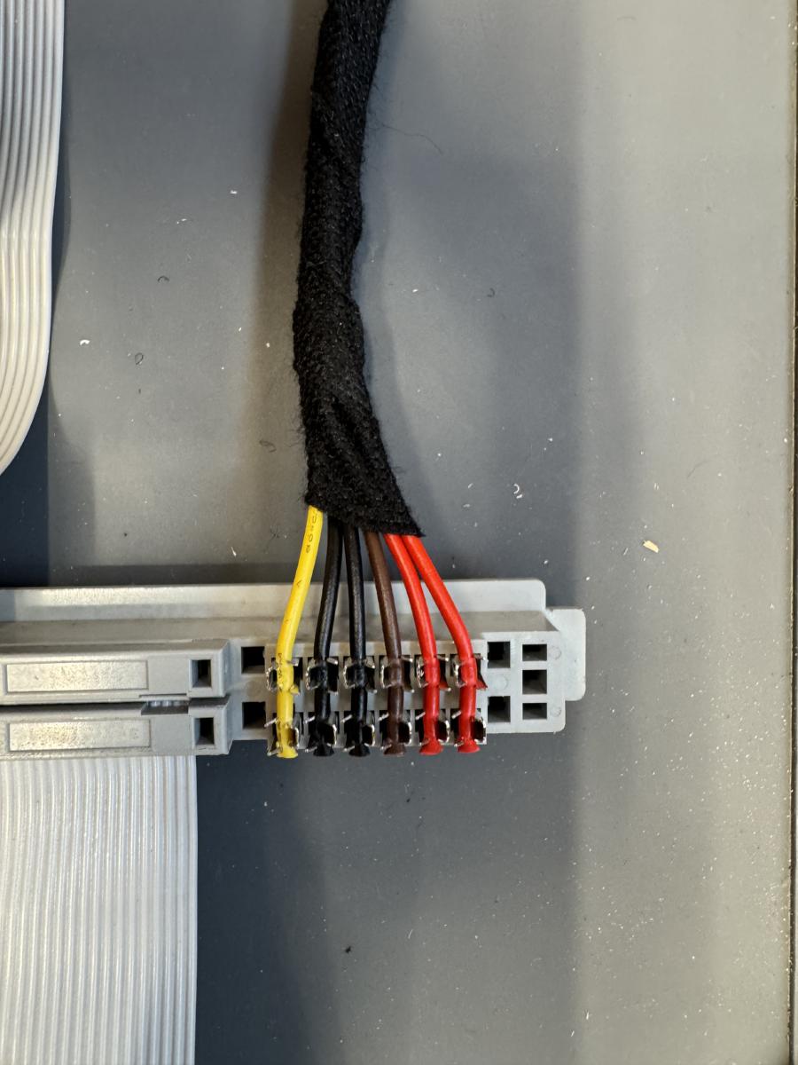
If the finalized cable looks like this you are ready to go!